Lumetra
Lumetra
Lumetra
Precision engineered connectivity solutions developed for advanced signal integrity, minimal crosstalk, and seamless network compatibility.
In the rapidly evolving landscape of global telecommunications and enterprise networking, high-speed data transmission demands robust and fault-tolerant physical layer infrastructure. As networks scale up to support 10Gbps (10GBASE-T) and beyond, electromagnetic interference (EMI) and radio frequency interference (RFI) present significant barriers to signal reliability. Standard unshielded twisted pair (UTP) systems are frequently inadequate in environments defined by high electromagnetic noise—such as factory floors, server rooms, and medical diagnostic bays. This necessitates the implementation of high-performance, CE Certified Shielded RJ45 Connectors.
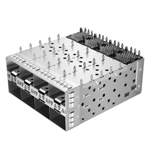
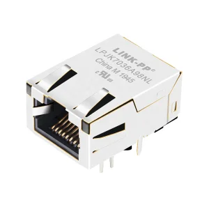
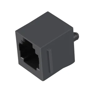
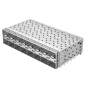
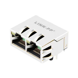
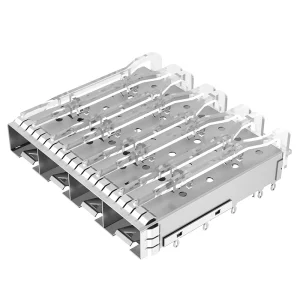
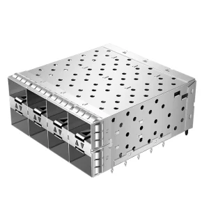
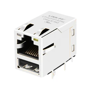
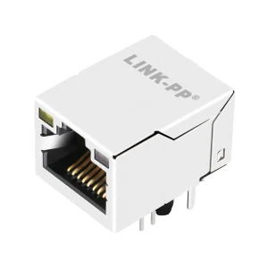
A shielded RJ45 connector, often integrated with standard or custom magnetic structures (MagJacks) or housed within multi-port SFP+ frames, provides a continuous Faraday cage surrounding the critical twisted copper pairs. By wrapping the modular jack in a metallic shell—typically constructed from nickel-plated brass or copper alloys—and grounding it to the cable's drain wire, signal integrity is preserved. The metallic shield acts as a barrier, absorbing external high-frequency waves and redirecting harmful common-mode noise away from the data lines. This ensures a dramatic reduction in Alien Crosstalk (ANEXT) and near-end crosstalk (NEXT), allowing the physical layer to maintain the low bit error rates (BER) demanded by high-speed, high-density environments.
360-degree metallic wrap effectively isolates differential signal pairs from high-frequency electromagnetic noise, preserving data packet integrity.
Rigorous compliance with European Standards (EN 55032/EN 55035) guarantees safety, signal control, and low radiated emissions.
Engineered to support Power over Ethernet applications up to 90W (IEEE 802.3bt), preventing terminal arcing and thermal breakdown.
Analyzing the macro-economic and engineering demands that guide procurement in global technology sectors.
The commercial landscape for shielded interconnects is expanding beyond the boundaries of traditional IT infrastructures. In modern industrial automation, the adoption of Industrial Ethernet protocols (such as EtherCAT, PROFINET, and Modbus TCP/IP) requires connectors that can withstand mechanical vibration, temperature swings, and severe electromagnetic interference caused by heavy motor drives, welding machinery, and variable frequency drives (VFDs). In these environments, unshielded plugs fail rapidly due to signal degradation and electrostatic discharge (ESD) events.
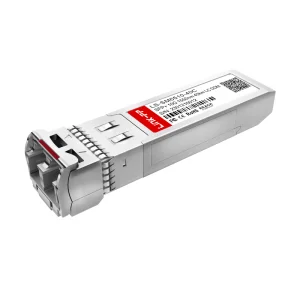
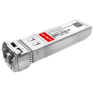
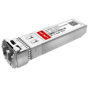
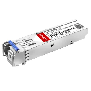
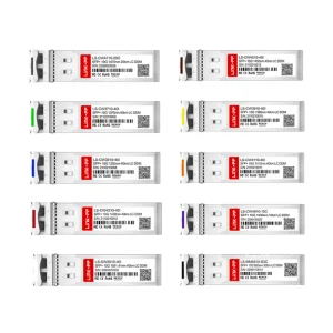
In the telecommunications sector, the roll-out of 5G small cells, Remote Radio Units (RRUs), and distributed antenna systems (DAS) relies heavily on outdoor-rated, shielded RJ45 assemblies. These connectors must defend high-frequency signals against interference from ambient RF transmissions while maintaining absolute physical integrity. Concurrently, hyper-scale cloud data centers operating 100G, 400G, and upcoming 800G pathways use complex SFP/SFP+ cage assemblies, stacked multi-port configurations, and active optical transceivers to pack maximum processing capacity into tight server rack footprints. Without precision-designed, CE certified shielding, the resulting signal path crosstalk would cripple data throughput.
| Application Scenario | Shielding Requirement | Common Connector Class | Key Standard Compliance | |
|---|---|---|---|---|
| Industrial Automation (Smart Factories, PLC Connections) | Dual Shielded (F/UTP or S/FTP) to resist VFD/motor noise | Cat6 / Cat6a Rugged Shielded RJ45 | IEC 60603-7, EN 50173-1 | CE, RoHS, UL 94V-0 |
| Enterprise Data Centers (Switching, Server Links) | 360° EMI cage grounding, low-profile SFP+ cages | Multi-port Stacked RJ45 / SFP+ integrated assemblies | IEEE 802.3an (10GBASE-T), SFF-8431 | CE, FCC Class B |
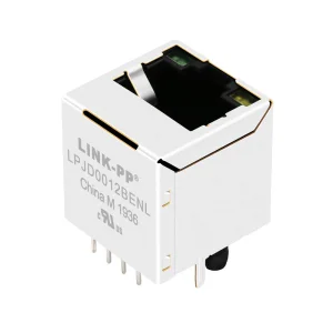
| Telecommunications FTTx (Edge Routing, Base Stations) | IP67 rated, weatherproofed shell + EMI shielding | Vertical Top-Entry Shielded RJ45 with Magnetics | IEEE 802.3ab (1000BASE-T) | CE, ITU-T Recommendations |
| Medical Diagnostic Systems (MRI, CT Scanning) | Non-magnetic shielding / Isolated shielding | Ultra-Low Noise Filtered RJ45 Jacks | IEC 60601-1 (Electrical Safety) | CE, FDA compliant materials |
Established in 2016, Lumetra Optoelectronics Technologies Co., Ltd. represents a synthesis of design innovation and manufacturing efficiency in high-performance optical communication, fiber-optic networking, and advanced copper interconnect systems. Boasting 11 years of structural industry experience alongside 7 years of active global export success, Lumetra provides high-grade solutions to telecommunications carriers, hyper-scale cloud datacenters, system integrators, and OEM/ODM clients in North America, Europe, Southeast Asia, and the Middle East.
Our state-of-the-art 8,500㎡ production facility enables tight control over the entire manufacturing workflow. From raw copper-alloy stamping and selective gold-electroplating to automated injection molding, magnetic winding insertion, and multi-stage testing, each phase is governed under ISO 9001 and ISO 14001 protocols. Backed by a robust network of more than 1,200 supply chain partners, Lumetra guarantees supply-chain resilience, offering stable cost models, custom molding, and accelerated lead times that shield clients from global market volatility.
Innovation is driven by our team of 86 R&D engineers, who specialize in physical hardware layout, mechanical stress engineering, high-frequency signal integrity simulation, and material science. This strong engineering focus allowed Lumetra to roll out over 220 new catalog products in the past year alone. This includes a comprehensive range of TE-compatible SFP+ cages, Pulse-compatible stacked RJ45 connectors, and low-profile magnetic jacks.
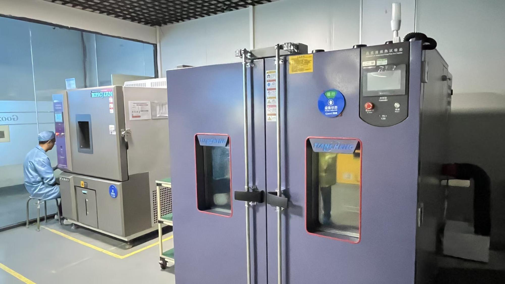
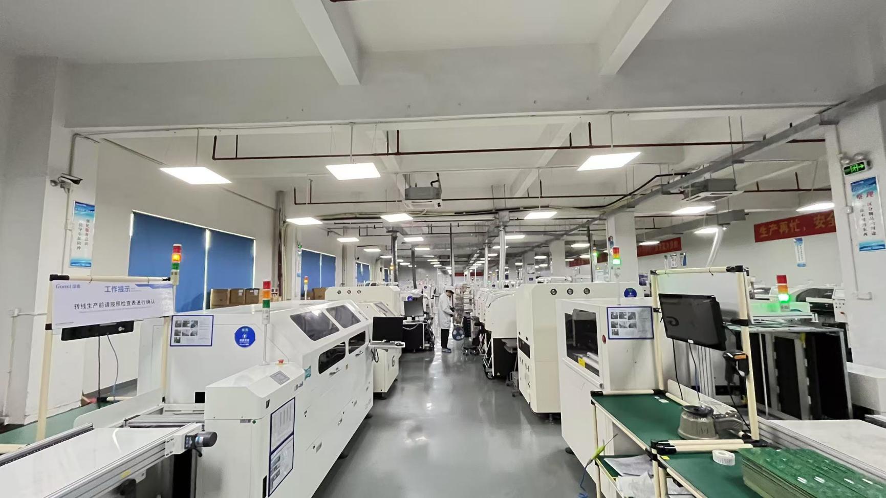
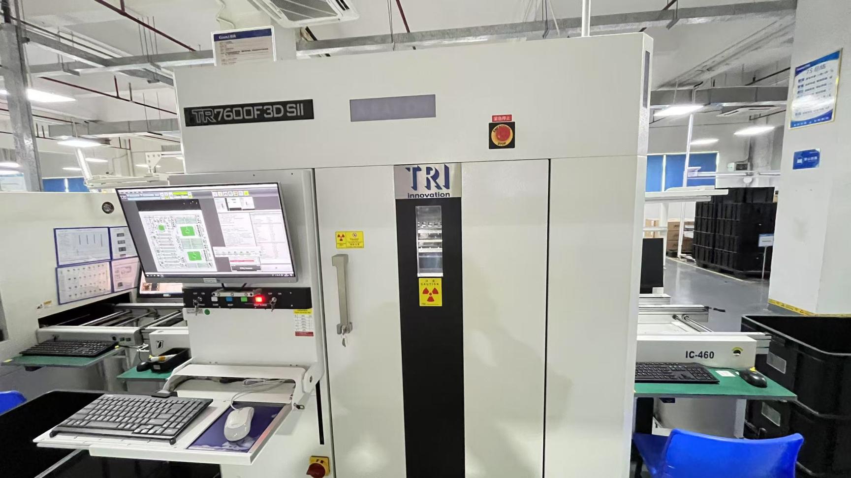
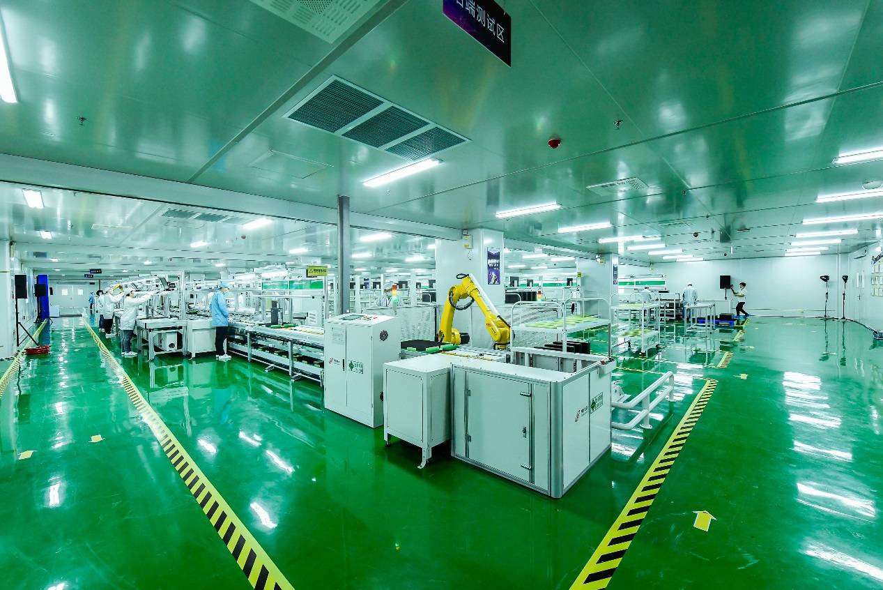
How Lumetra engineers reliability and performance into every single copper and optical contact.
Every shielded RJ45 connector and SFP+ assembly manufactured at Lumetra undergoes a battery of automated electrical characterization tests. Our quality control division, which includes 48 trained inspectors, utilizes high-end network analyzers and digital sampling oscilloscopes to measure critical transmission parameters. We test for insertion loss (attenuation of the signal as it travels through the connector), return loss (reflections of signal energy caused by impedance mismatches), and near-end/far-end crosstalk (NEXT/FEXT). By keeping these measurements far below standard-mandated limits, our connectors maintain stable connections under extreme real-world network loads.
To prevent oxidation, wear, and elevated contact resistance over time, Lumetra uses 50μ" gold-over-nickel plating on phosphor bronze contacts. The outer shield is constructed from high-tensile brass or copper alloys finished with a uniform layer of bright nickel plating, ensuring reliable grounding to the mating cable shield. The internal housing is molded from high-performance thermoplastics rated to UL 94V-0, guaranteeing self-extinguishing behavior and excellent thermal resistance. This material profile allows our components to support high-density PoE/PoE++ cabling without thermal deformation or structural failure.
Understanding that standard off-the-shelf connectors do not fit every custom housing, Lumetra provides complete OEM/ODM design services. Our R&D team works closely with enterprise hardware engineers to design specialized layouts, modify terminal tail designs (Through-hole, Press-Fit, SMT), customize integrated LED colors, and tune internal magnetics to achieve unique impedance profiles.
Detailed answers to complex technical questions frequently asked by hardware engineers, network architects, and procurement managers.
Complete physical-layer hardware selection including optical transceivers, vertical jacks, and modular network assemblies.