Lumetra
Lumetra
Lumetra
Direct supply from state-of-the-art manufacturing lines ensuring maximum signal integrity and protocol compatibility.
Meeting the Demands of Edge Computing, IoT Deployment, and High-Speed Optical Architectures
As structured cabling deployments face strict physical space limitations and cost-containment directives, the need for reliable passive networking infrastructure has accelerated globally. An Ethernet Splitter acts as a physical layer utility, dividing a single 8-pin Category 5e, Cat 6, or Cat 6a run into two distinct physical lines (traditionally utilized in pairs). This approach enables transmission channels over 10/100Base-T configurations by leveraging the alternate pairs (pins 1-2-3-6) within standard Ethernet cabling.
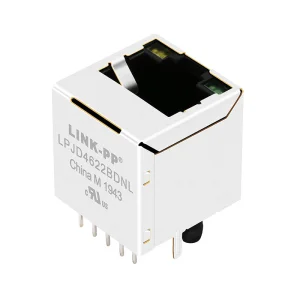
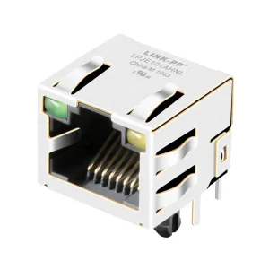
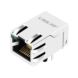
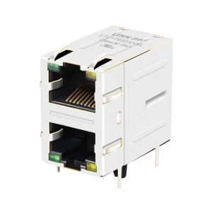
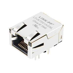
In addition to simple passive copper splitting, modern enterprise environments demand specialized integration at the silicon and magnetic level. Incorporating low-profile RJ45 jacks with integrated magnetics (LAN filters) minimizes electromagnetic interference (EMI) and crosstalk. This layout configuration is vital when handling PoE (Power over Ethernet) runs, where physical lines must handle both continuous power loads and high-speed data streams without signal degradation.
Addressing System Interoperability, Long-Term Reliability, and Strict Supply Chain Quality
Global distributors require direct validation that components meet environmental and safety directives including RoHS, REACH, CE, and FCC. Our factory guarantees complete compliance audits down to raw raw materials, eliminating procurement risk.
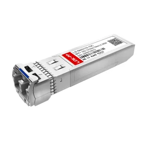
Telecom equipment designs often require specific hardware configurations, including modified footprint layouts, customized LED channels, tab placement directions, or distinct optical wavelengths (1310nm, 1550nm, BiDi) to support legacy system designs.
Whether routing copper lines through RJ45 magnetic splitters or deploying optical transceivers for long-haul networks, maintaining high return loss margins and minimizing crosstalk is critical for network reliability and performance.
Bridging High-Speed Optical Data Center Cores with Localized Copper Ethernet Interfaces
Industrial networking designs are rarely homogeneous. Modern topologies utilize optical fiber pipelines to connect disparate equipment centers across distances, converting to copper cabling endpoints for cost-effective distribution. Deploying premium components ensures that translation boundaries do not introduce data bottlenecks.
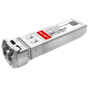
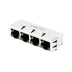
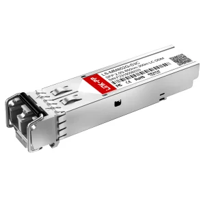
For instance, high-speed SFP modules support long-distance transport (up to 120km with BiDi modules), while custom PCB interfaces configured with low-profile magnetic RJ45 connectors distribute data feeds directly to end devices. When layout restrictions limit port availability, specialized Ethernet splitters and multiport connectors (such as 1x4 and 2x1 models) provide high density without expanding the system footprint.
Common Deployment Topologies:
Technical Specifications and High-Volume OEM/ODM Capability Standards
| Functional Category | Manufacturing & Engineering Specifications | Target Network Applications |
|---|---|---|
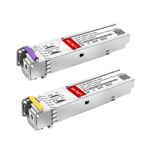
| Optical Transceivers | 2.5G SFP, 10G SFP+, BiDi Simplex LC up to 120km, Duplex SMF/MMF | Enterprise Telecom, Hyperscale Data Centers, Cloud Backhaul |
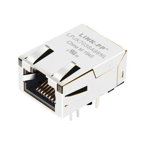
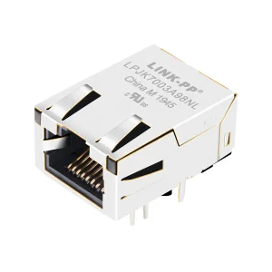
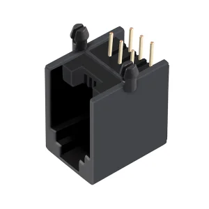
| Integrated RJ45 Connectors | 10/100/1000 Base-T, Low Profile, Tab Up/Down, Integrated Magnetics & LEDs | Network Routing Hardware, Industrial PCs, Custom IoT Gateways |
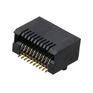
| Multi-Port RJ45 Form Factors | 1x4 and 2x1 Modular Jacks with LED configurations, Shielded / Unshielded | High-Density Switch Ports, Hub Assemblies, Network Interfaces |
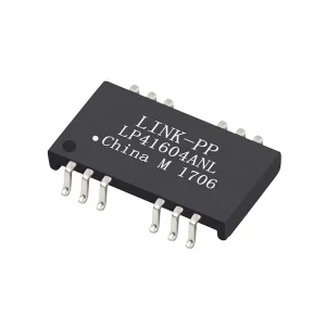
| LAN Magnetic Filters | Surface Mount (SMD) Ethernet Transformers, Custom Turn Ratios | Signal Path Noise Filtering, Isolation Barrier Protection |
| R&D Specialization | 86 In-house Engineers, Protocol Matching, Laser Wavelength Tuning | Bespoke Proprietary Equipment, Special OEM Hardware Integration |
Engineering Interconnect Solutions for Tomorrow's High-Speed Standards
Developing advanced magnetic designs for RJ45 assemblies capable of supporting multi-gigabit copper speeds with clean signal compliance.
Collaborating with leading semiconductor vendors to integrate optical transceiver lines directly onto processor packages to minimize power draw.
Optimizing magnetic cores to handle up to 90W-100W PoE++ (IEEE 802.3bt) configurations without core saturation or excessive heat build-up.
Integrating optical performance monitoring directly into module firmware for real-time tracking of parameters like power, bias current, and temperature.
E-E-A-T Certified Infrastructure: Lumetra Optoelectronics Technologies Co., Ltd.
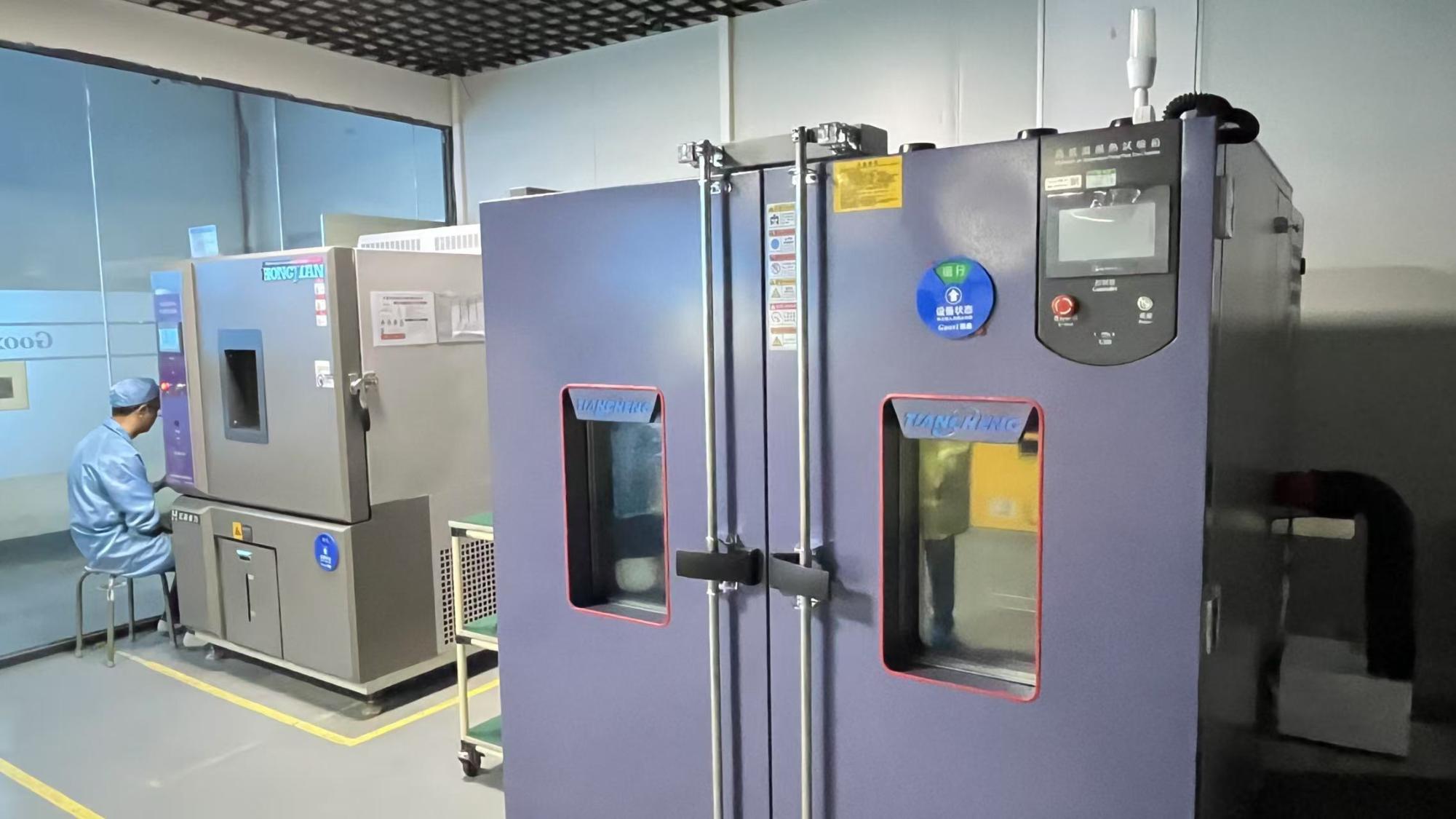
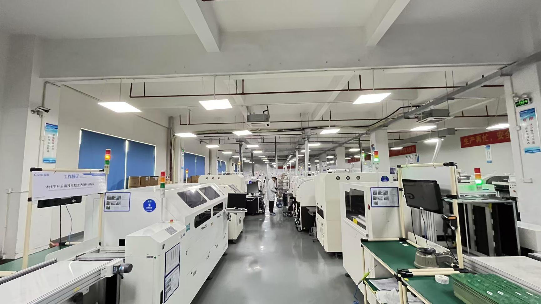
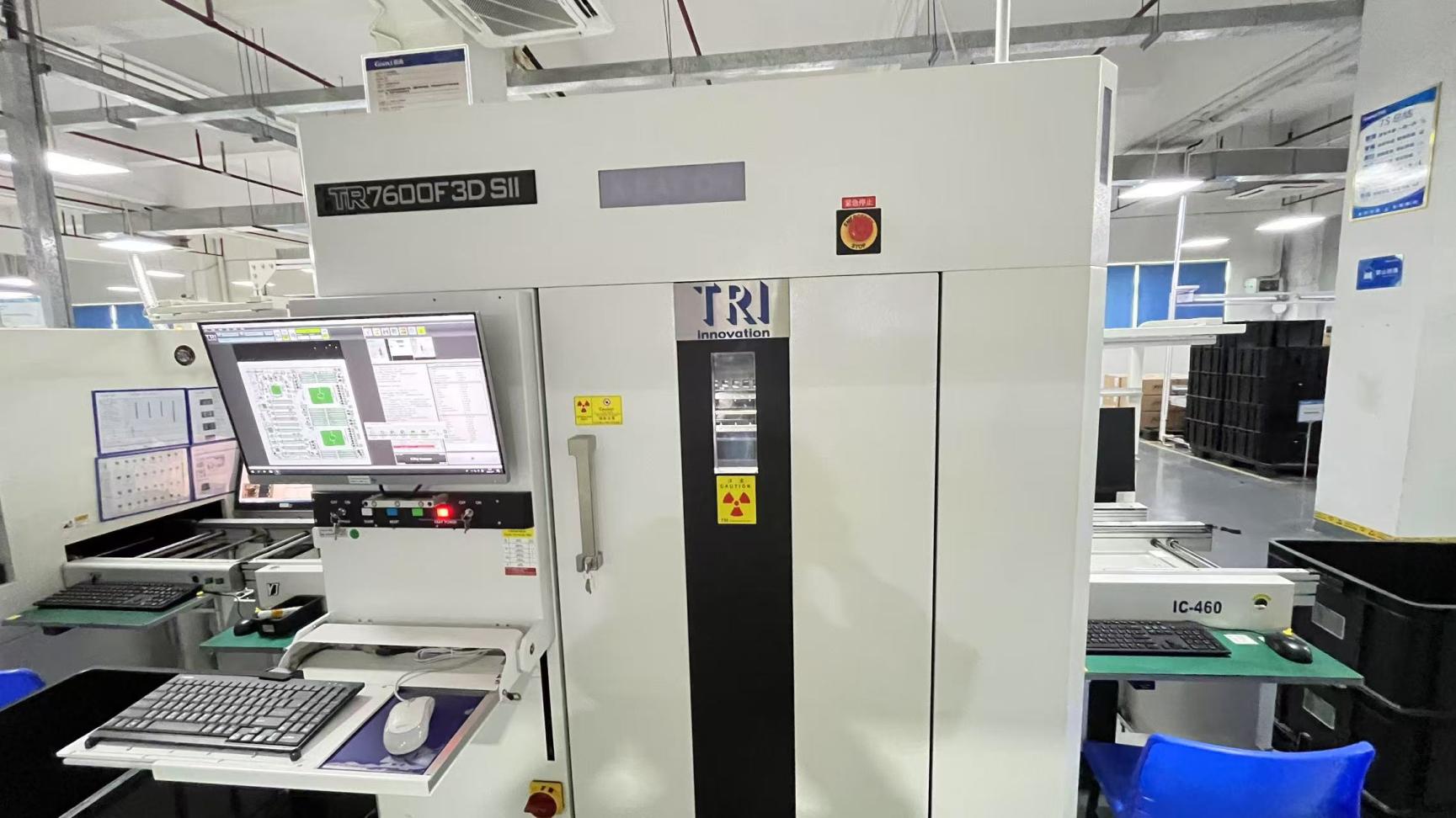
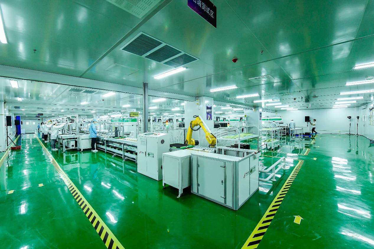
Founded in 2016, Lumetra operates an 8,500㎡ production facility optimized for efficiency and strict quality-controlled assembly. Supported by 48 trained inspectors, the quality assurance team maintains zero-defect protocols using a combination of automated optical performance testing, environmental stress screening, and manual inspection.
With 11 years of overall industry expertise and 7 years of international trade experience, our technical support extends to regional hubs in North America, Europe, Southeast Asia, and the Middle East. Over 1,200 supply chain partners ensure components meet all specifications, providing stable supply chains even during times of market volatility.
Compliance & Certifications Matrix:
With 86 R&D engineers focused on optical design, physical hardware development, and signal integrity optimization, our factory handles complex customization requirements. Whether adapting form factors, tuning specific wavelengths, or adjusting compatibility protocols, our engineering team ensures seamless design integration.
Our active product catalog continues to expand, with approximately 220 new products launched in the past year. This commitment to ongoing innovation helps ensure that our customers have access to the latest networking interface designs.
Our FAE (Field Application Engineering) department can review your layouts and provide simulation reports to verify electrical performance before production begins.
Direct Engineering Answers for Network System Architects and Sourcing Directors
Reliable components designed for high-density layouts and industrial network systems.